The Press Brake
Press brake bending it's a DEFORMATION process obtain through a FORCE applied on a given MATERIAL.
We tend to forget about this simple statement. There's a reason for the word PRESS in our machines. They apply pressure.. well, they apply force which becomes pressure over the area of the sheet we are bending.
This means that the deformation happens on a small portion of the sheet. That portion which falls inside the V opening and it's in contact with the upper tool radius.


We use CNC PB with servo valves so we can control the ram position, its force and straightness.
In our modern CNC brakes most of the time we are air bending.
This means that after some initial resistance from the sheet, the rest of the deformation is about reaching the point on which we will obtain our desired angle.
So what matters is the distance the ram travels, not only the force that it's applied.
What matters is the exact distance the ram travels.
Our ram must reach an exact point in order to obtain a certain angle on the sheet

Let's run some simulation to understand this better:
On a V=1" (25mm) every .019" (0,5mm) the ram comes down our part closes more than 2°!!!!
Demonstration
In this V=24mm the 90° sheet bend forms the 45° as part of the triangle shown in solid line.
x and y have the same length and h is 1.414 times x or y (thanks Pitagora for this hint).
Trig ratios always stay the same on right triangles. This is a right triangle and the trig ratio we are interested on is:
Tangent = Opposite/Adjacent
Why? we want to see what happens when y is increased by ^y. Please note that x does not increase, and that is why our angle becomes acute.
But how much ^y is needed for every angle degree closed?
Well.... since trig ratios stay the same we can calculate this:
x=12 (half the V opening)
y=12
h=17
^y=0,5
so... on the new angle (let's call it B) we have:
Tan(B) = 12/12,5 (x/y+^y) = 0,96.. which is the tangent of 43,83° (i used the calculator for that my friend)
Which means that by increasing the ram travel by 0,5mm (.019") we closed our part by over 2° (the triangle is only half of our part bending)
This gives us the idea of how precise every movement of the ram must be in order to obtain correct bends.
To complicate things further we will need to deal with material spring-back which will affect the angle, the radius and the blank we need to cut.
The press brake CNC will calculate the ram travel and adjust for the spring-back, but the radius and the blank might be another story, since that's also related to the V opening used.
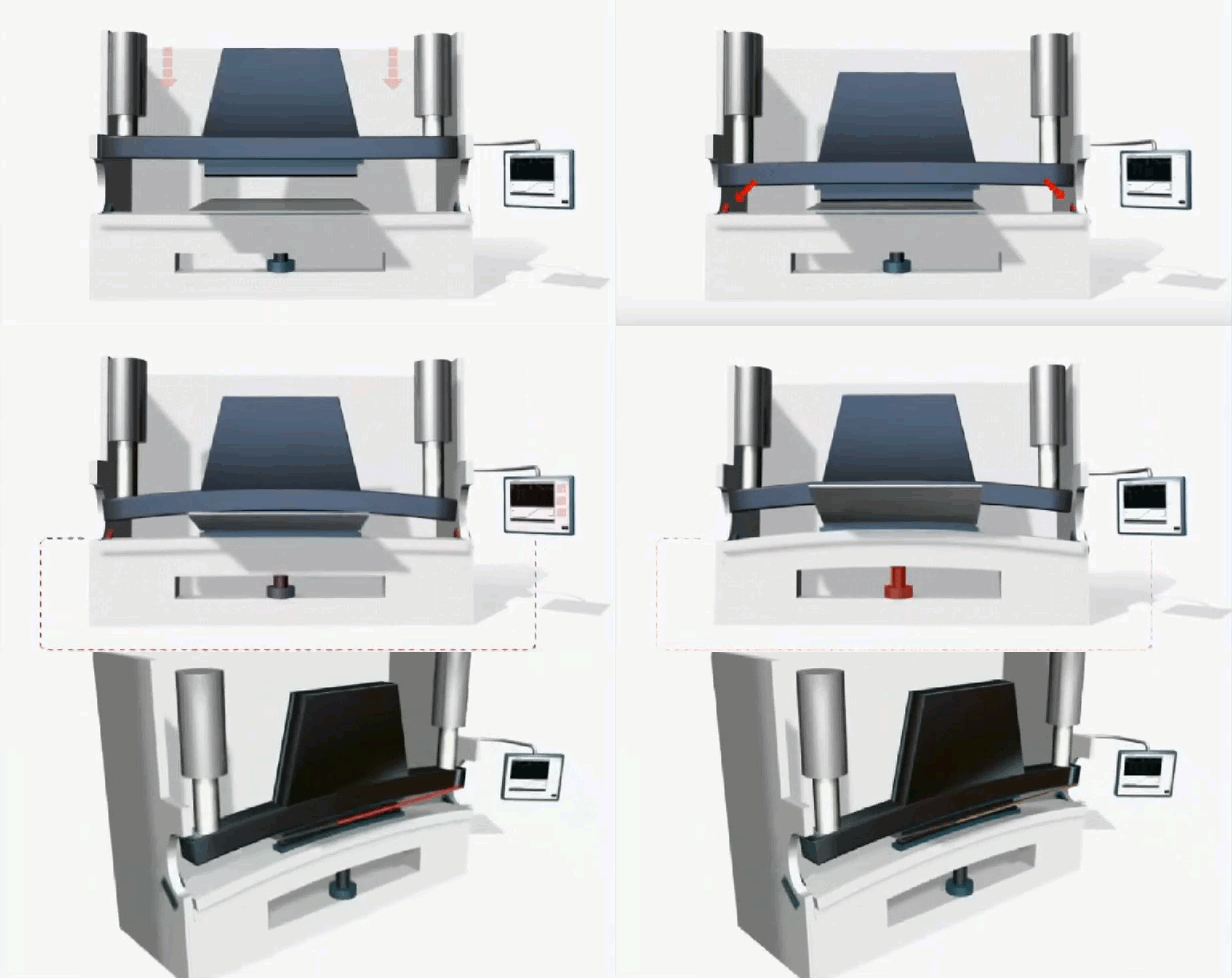
Crowning & Y1 - Y2

The force applied by a PB comes from 2 cylinders, positioned one at each end of the brake (we have electrical PB nowadays, but the most common machines are still hydraulic PB).
Since the force is applied on the cylinders, called Y1 & Y2, when they are further apart than 8ft (2,5mtr) the center part of the brake receives less force and so the structure of the complete PB bows, creating a gap in the middle point of the brake.
This is the reason parts usually are wider opened in the center than on both ends. This is why all old brakes have shims of some kind in under the bottom die in that portion of the PB.
We compensate this deformation using a crowning system.
Crownings can be mechanical or hydraulic.
The mechanical crowning works by 2 counter wedges that slice one over the other. This creates a shimming effect in the middle length of the brake that compensates for the deformation occurred during Y1 & Y2 applying force.
The hydraulic crowning on the other hand has some cylinders (usually 3) in the bottom table structure. The pistons in the table apply their force upwards to compensate the deformation from Y1 & Y2 pushing down.
Backgauge


We all know those fabricators bragging about his 12 axis PB. BUT when inquired they don't actually know what all those axis are.
We know that Y1 & Y2 are the main 2 axis on any CNC PB.. those are the 2 cylinders pushing down.
The other axis we are most interested on are surely the back-gauge axis.
Once we know how these can help us on our fabrication process we can move on to other xis like sheet folder followers or automatic tool changers....
How do they help us?
X axis move the back-gauge back and forward. This is the basic axis we need the BG to travel. being CNC controlled it will help us position the sheet to the exact length of each flange.
Moving independently (X1&X2) come handy when bending tapered sheet or conical poles.
Z axis move laterally from operators perspective. Moving independently and by CNC is a game changer when doing stage bend (multiple tooling setups on the PB and operator moving from one to the next to complete a part)
R axis move the fingers up and down, which is useful for odd parts where our reference point is not on the same height as the bending area or when performing a "bumping" operation
